

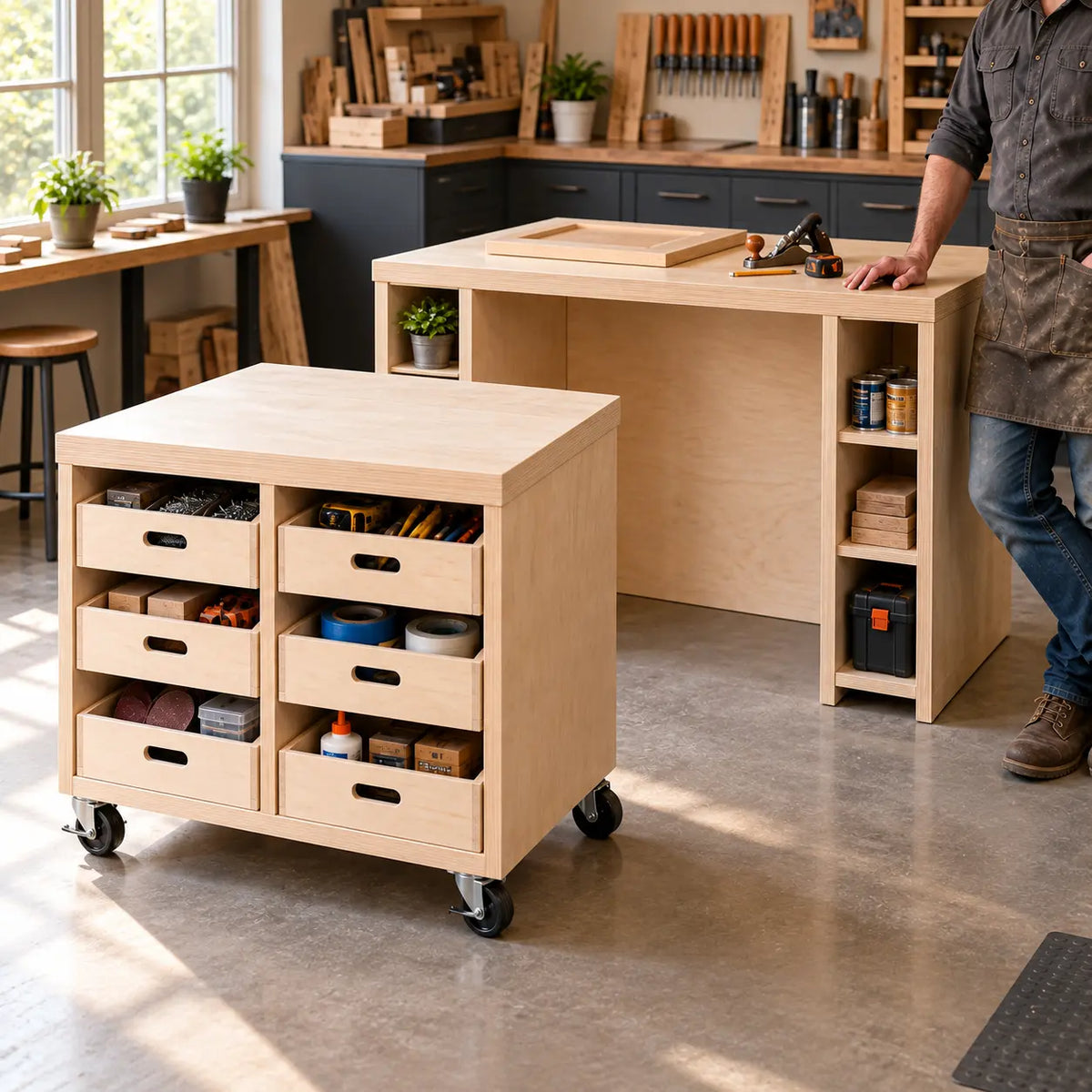
Two work zones. One parking space.
A small workshop often needs an extra surface only while a project is in progress. Fivalo™ NestDock Duo gives you a fixed storage workbench and a separate rolling project cart that parks inside it. Pull the cart clear, lock the casters, and keep your layout tools or assembly parts beside the work. At the end of the session, return all six removable task trays and roll the cart home.
This guide includes the materials, hardware, finished dimensions in inches and millimeters, all 73 wood parts, five plywood cutting layouts, an exploded view, and 12 illustrated construction steps. The realistic cover is an AI-generated design visualization; the technical diagrams and written measurements control the build.
Prototype edition: the geometry and cutting layouts have been digitally checked. The project has not yet been physically built or load-tested, and no working load is assigned. Confirm actual plywood thickness and caster fit before cutting, then complete the physical checks in Step 12.
Download the printable 22-page plan (PDF)
| Project detail | Specification |
|---|---|
| Skill level | Intermediate: accurate sheet cutting, square cabinet assembly and through-bolted casters. |
| Build time | 20–28 hands-on hours, plus glue and finish cure time; roughly three working days. |
| Parked footprint | 48" × 24" / 1219.2 × 609.6 mm W × D |
| Dock working height | 36" / 914.4 mm |
| Cart working height | 34" / 863.6 mm |
| Storage | Six removable trays and two fixed shelf towers. |
| Intended use | Layout, light assembly and tool organization on a firm, flat indoor floor. |
How the nesting workstation works
The fixed dock holds the main worktop and narrow shelf towers. The cart carries a second worktop over six interchangeable trays that slide on hardwood runners. There are no drawer slides or folding mechanisms to synchronize: the entire cart rolls straight out, and each tray lifts away to become a carry box.
Use the trays for layout, drilling, joinery, fastening, sanding and assembly supplies. Move the cart to the project with every tray fully seated. Once it is completely clear of the dock, turn it into position and lock all four casters before working.


Finished dimensions and clearances
| Component / clearance | Inches and millimeters |
|---|---|
| Dock — width × depth × height | 48" × 24" × 36" / 1219.2 × 609.6 × 914.4 mm |
| Cart — width × depth × height | 30 1/2" × 23" × 34" / 774.7 × 584.2 × 863.6 mm |
| Central parking opening — width × depth × height | 31 1/2" × 23 1/2" × 34 1/2" / 800.1 × 596.9 × 876.3 mm |
| Nominal nesting gap at each side, above and behind | 1/2" / 12.7 mm |
| Laminated top thickness | 1 1/2" / 38.1 mm |
| Each side tower — clear width × depth | 6 3/4" × 23 1/2" / 171.45 × 596.9 mm |
| Tower clear shelf-to-shelf openings | 9 3/4" / 247.65 mm and 10 1/2" / 266.7 mm |
| Upper tower opening at center / below edge cleats | 10 1/2" / 266.7 mm / 9 3/4" / 247.65 mm |
| Each cart bay — clear width × depth × body height | 14 1/8" × 21 1/2" × 27 1/2" / 358.775 × 546.1 × 698.5 mm |
| Each tray — outside width × depth × height | 13 7/8" × 20 1/2" × 4 1/2" / 352.425 × 520.7 × 114.3 mm |
| Each tray — inside width × depth × height | 12 7/8" × 19 1/2" × 4" / 327.025 × 495.3 × 101.6 mm |
| Tray side clearance / runner bearing per side | 1/8" / 3.175 mm clearance; 5/8" / 15.875 mm bearing |
| Tray bottom heights from floor | 7 1/4" / 184.15 mm, 15 1/4" / 387.35 mm, 23 1/4" / 590.55 mm |
| Runner pitch | 8" / 203.2 mm |
| Clear access in front of dock | At least 36" / 914.4 mm; allow more for the task. |

Inches control this edition. Every metric value is converted at 25.4 mm per inch. Treat the paired measurements as one system: do not independently round each part and then expect the original gaps. All cut dimensions are finished sizes, without edge banding.
Materials and hardware
- 3 sheets cabinet-grade birch veneer-core plywood, each 48" × 96" × 3/4" / 1219.2 × 2438.4 × 19.05 mm; measured true thickness 3/4" / 19.05 mm. Straight, flat panels with sound edges.
- 2 sheets birch plywood, each 48" × 96" × 1/2" / 1219.2 × 2438.4 × 12.7 mm; measured true thickness 1/2" / 12.7 mm. These provide both shear backs and all six trays.
- 3 straight maple/beech square lengths, each 96" × 3/4" × 3/4" / 2438.4 × 19.05 × 19.05 mm; cut four N from each. Do not substitute an undersized nominal dowel.
- 4 total-lock swivel casters matching the complete purchase envelope in the engineering notes. Wheel 3" / 76.2 mm, installed height 4 1/4" / 107.95 mm. Hardware thickness/plate geometry must match the measured supplied item.
- 48 used, buy 75: #8 cabinet/wood screws, 1 3/4" / 44.45 mm long; nominal major diameter 0.164" / 4.1656 mm. No drywall screws.
- 119 used, buy 150: #8 cabinet/wood screws, 1 1/4" / 31.75 mm long; nominal major diameter 0.164" / 4.1656 mm. Flat head for flush wood fastening.
- 108 used, buy 125 or 150: #6 wood screws, 1" / 25.4 mm long; nominal major diameter 0.138" / 3.5052 mm. Do not substitute longer screws in tray corners.
- 16 steel hex bolts, 5/16-18 UNC (major diameter 5/16" / 7.9375 mm, pitch 1/18" / 1.4111 mm), 2 1/2" / 63.5 mm under-head length; 16 matching nylon-insert locknuts; 32 flat washers, nominal bore 11/32" / 8.7312 mm, OD 7/8" / 22.225 mm, thickness 1/16" / 1.5875 mm. Verify at least two full threads beyond the seated nut and no wheel/yoke interference. Use the caster maker’s torque guidance.
- PVA interior woodworking glue, approximately 1 US quart / 0.95 L purchasing allowance; follow label spread and full-cure times. Glue amount varies with product and waste.
- Water-based clear polyurethane, approximately 1 US quart / 0.95 L purchasing allowance; thin coats on both faces and edges per label. Dry-film thickness is product-dependent and is not a structural layer. Keep glue faces bare until assembly.
- Small tin of furniture paste wax for runner bearing faces after finish cure; masking tape, sanding abrasives and shop rags. No added edge banding, padding or leveling hardware in the dimensional stack.
The caster dimensions are a purchase acceptance envelope, not a verified retail model. Obtain all four identical casters and check their supplier drawing and physical measurements before cutting. A wheel diameter alone does not establish overall height or brake clearance.
Recommended tools
- Track saw or circular saw with straight guide; table saw optional. Use a blade whose measured kerf is no more than 1/8" / 3.175 mm for this nesting layout.
- Drill/driver, countersink, drill stops, combination square, tape, caliper, straightedge and two long parallel clamps plus assembly clamps.
- Pilot starting points in scrap: #8 screws 7/64" / 2.7781 mm; #6 screws 3/32" / 2.3812 mm. Clearance holes in the FIRST member only: #8 11/64" / 4.3656 mm, #6 5/32" / 3.9688 mm. Adjust pilots to actual screw root and wood; countersink flush without weakening the face.
- Caster through-hole bit 11/32" / 8.7312 mm for 5/16" / 7.9375 mm bolts. Hand-slot bit 1 1/4" / 31.75 mm plus jigsaw/router and backing board. Orbital sander, 120/180/220 grit; hearing/eye protection and dust extraction.
The Fivalo 90 Degree Corner Clamp can hold shelf and tray corners while you check them for square and apply the main clamping pressure with longer clamps. It is useful in Steps 2 and 10.
Also have two wrenches for the caster bolts, a glue roller, clean cauls, a wax applicator and a stable assembly surface ready.
Master cut list — 73 wood parts
Label each part before assembly. The first two dimensions below are the face dimensions; use the part name and grain note to determine orientation. All edges are square at 90°. Part ID O is intentionally unused.
| Part ID and name | Qty | Length × width × thickness | Material / grain / notes |
|---|---|---|---|
| A — Dock top layer | 2 | 48" × 24" × 3/4" / 1219.2 × 609.6 × 19.05 mm | Birch plywood; Laminate two; grain along width. |
| B — Dock outer side | 2 | 34 1/2" × 23 1/2" × 3/4" / 876.3 × 596.9 × 19.05 mm | Birch plywood; Grain vertical; square ends. |
| C — Dock inner divider | 2 | 34 1/2" × 23 1/2" × 3/4" / 876.3 × 596.9 × 19.05 mm | Birch plywood; Grain vertical; square ends. |
| D — Dock shear back | 1 | 48" × 34 1/2" × 1/2" / 1219.2 × 876.3 × 12.7 mm | Birch plywood; Applied back; grain horizontal. |
| E — Side-tower shelf | 6 | 6 3/4" × 23 1/2" × 3/4" / 171.45 × 596.9 × 19.05 mm | Birch plywood; Grain across short shelf span. |
| F — Cart top layer | 2 | 30 1/2" × 23" × 3/4" / 774.7 × 584.2 × 19.05 mm | Birch plywood; Laminate two; grain across width. |
| G — Cart side | 2 | 27 1/2" × 21 1/2" × 3/4" / 698.5 × 546.1 × 19.05 mm | Birch plywood; Grain vertical; sits on H. |
| H — Cart base | 1 | 30 1/2" × 22" × 3/4" / 774.7 × 558.8 × 19.05 mm | Birch plywood; Full width; supports G and J. |
| I — Cart shear back | 1 | 30 1/2" × 27 1/2" × 1/2" / 774.7 × 698.5 × 12.7 mm | Birch plywood; Applied back; grain horizontal. |
| J — Cart divider | 1 | 27 1/2" × 21 1/2" × 3/4" / 698.5 × 546.1 × 19.05 mm | Birch plywood; Centered across cart width. |
| K — Tray side | 12 | 20 1/2" × 4" × 1/2" / 520.7 × 101.6 × 12.7 mm | Birch plywood; Two per tray; runs full depth. |
| L — Tray end | 12 | 12 7/8" × 4" × 1/2" / 327.025 × 101.6 × 12.7 mm | Birch plywood; Two per tray; between K. Six fronts get slots. |
| M — Tray bottom | 6 | 13 7/8" × 20 1/2" × 1/2" / 352.425 × 520.7 × 12.7 mm | Birch plywood; Applied below walls; grain across width. |
| N — Tray runner | 12 | 20 1/2" × 3/4" × 3/4" / 520.7 × 19.05 × 19.05 mm | Straight maple or beech; Square stock; no edge radius on bearing face. |
| P — Caster reinforcement | 4 | 5" × 5" × 3/4" / 127 × 127 × 19.05 mm | Birch plywood; Glue on upper face of H. |
| Q — Top fixing cleat | 7 | 20" × 1 1/2" × 3/4" / 508 × 38.1 × 19.05 mm | Birch plywood; Four dock; three cart. Wide face horizontal. |
Plywood cutting diagrams
The checked layout uses three sheets of true 3/4" / 19.05 mm plywood and two sheets of true 1/2" / 12.7 mm plywood. Each sheet is 96" × 48" / 2438.4 × 1219.2 mm. Allow a 1/8" / 3.175 mm kerf and trim 1/8" / 3.175 mm from every perimeter edge. The resulting usable rectangle is 95 3/4" × 47 3/4" / 2432.05 × 1212.85 mm.
On every sheet diagram, X follows the long grain direction and Y runs across the sheet. Start at the original lower-left sheet corner. Coordinates locate the lower-left corner of each finished part, after trim. Keep the blade on the waste side and use the shown strip order; do not subtract the kerf again from a finished part size.
Sheet 1 — 3/4" / 19.05 mm plywood
Parts: A × 1, F × 1, E × 5, B × 1, C × 1. Grain follows X on the diagram.

Open exact sheet 1 coordinates
| Part / instance | X from sheet left | Y from sheet bottom | Size along X × Y |
|---|---|---|---|
| A-1 | 1/8" / 3.175 mm | 1/8" / 3.175 mm | 48" × 24" / 1219.2 × 609.6 mm |
| F-1 | 48 1/4" / 1225.55 mm | 1/8" / 3.175 mm | 30 1/2" × 23" / 774.7 × 584.2 mm |
| E-1 | 78 7/8" / 2003.425 mm | 1/8" / 3.175 mm | 6 3/4" × 23 1/2" / 171.45 × 596.9 mm |
| E-2 | 85 3/4" / 2178.05 mm | 1/8" / 3.175 mm | 6 3/4" × 23 1/2" / 171.45 × 596.9 mm |
| B-1 | 1/8" / 3.175 mm | 24 1/4" / 615.95 mm | 34 1/2" × 23 1/2" / 876.3 × 596.9 mm |
| C-1 | 34 3/4" / 882.65 mm | 24 1/4" / 615.95 mm | 34 1/2" × 23 1/2" / 876.3 × 596.9 mm |
| E-3 | 69 3/8" / 1762.125 mm | 24 1/4" / 615.95 mm | 6 3/4" × 23 1/2" / 171.45 × 596.9 mm |
| E-4 | 76 1/4" / 1936.75 mm | 24 1/4" / 615.95 mm | 6 3/4" × 23 1/2" / 171.45 × 596.9 mm |
| E-5 | 83 1/8" / 2111.375 mm | 24 1/4" / 615.95 mm | 6 3/4" × 23 1/2" / 171.45 × 596.9 mm |
Sheet 2 — 3/4" / 19.05 mm plywood
Parts: A × 1, F × 1, E × 1, B × 1, C × 1. Grain follows X on the diagram.

Open exact sheet 2 coordinates
| Part / instance | X from sheet left | Y from sheet bottom | Size along X × Y |
|---|---|---|---|
| A-2 | 1/8" / 3.175 mm | 1/8" / 3.175 mm | 48" × 24" / 1219.2 × 609.6 mm |
| F-2 | 48 1/4" / 1225.55 mm | 1/8" / 3.175 mm | 30 1/2" × 23" / 774.7 × 584.2 mm |
| E-6 | 78 7/8" / 2003.425 mm | 1/8" / 3.175 mm | 6 3/4" × 23 1/2" / 171.45 × 596.9 mm |
| B-2 | 1/8" / 3.175 mm | 24 1/4" / 615.95 mm | 34 1/2" × 23 1/2" / 876.3 × 596.9 mm |
| C-2 | 34 3/4" / 882.65 mm | 24 1/4" / 615.95 mm | 34 1/2" × 23 1/2" / 876.3 × 596.9 mm |
Sheet 3 — 3/4" / 19.05 mm plywood
Parts: H × 1, G × 2, J × 1, P × 4, Q × 7. Grain follows X on the diagram.

Open exact sheet 3 coordinates
| Part / instance | X from sheet left | Y from sheet bottom | Size along X × Y |
|---|---|---|---|
| H-1 | 1/8" / 3.175 mm | 1/8" / 3.175 mm | 30 1/2" × 22" / 774.7 × 558.8 mm |
| G-1 | 30 3/4" / 781.05 mm | 1/8" / 3.175 mm | 27 1/2" × 21 1/2" / 698.5 × 546.1 mm |
| J-1 | 58 3/8" / 1482.725 mm | 1/8" / 3.175 mm | 27 1/2" × 21 1/2" / 698.5 × 546.1 mm |
| G-2 | 1/8" / 3.175 mm | 22 1/4" / 565.15 mm | 27 1/2" × 21 1/2" / 698.5 × 546.1 mm |
| P-1 | 27 3/4" / 704.85 mm | 22 1/4" / 565.15 mm | 5" × 5" / 127 × 127 mm |
| P-2 | 32 7/8" / 835.025 mm | 22 1/4" / 565.15 mm | 5" × 5" / 127 × 127 mm |
| P-3 | 38" / 965.2 mm | 22 1/4" / 565.15 mm | 5" × 5" / 127 × 127 mm |
| P-4 | 43 1/8" / 1095.375 mm | 22 1/4" / 565.15 mm | 5" × 5" / 127 × 127 mm |
| Q-1 | 27 3/4" / 704.85 mm | 27 3/8" / 695.325 mm | 20" × 1 1/2" / 508 × 38.1 mm |
| Q-2 | 27 3/4" / 704.85 mm | 29" / 736.6 mm | 20" × 1 1/2" / 508 × 38.1 mm |
| Q-3 | 27 3/4" / 704.85 mm | 30 5/8" / 777.875 mm | 20" × 1 1/2" / 508 × 38.1 mm |
| Q-4 | 27 3/4" / 704.85 mm | 32 1/4" / 819.15 mm | 20" × 1 1/2" / 508 × 38.1 mm |
| Q-5 | 27 3/4" / 704.85 mm | 33 7/8" / 860.425 mm | 20" × 1 1/2" / 508 × 38.1 mm |
| Q-6 | 27 3/4" / 704.85 mm | 35 1/2" / 901.7 mm | 20" × 1 1/2" / 508 × 38.1 mm |
| Q-7 | 27 3/4" / 704.85 mm | 37 1/8" / 942.975 mm | 20" × 1 1/2" / 508 × 38.1 mm |
Sheet 4 — 1/2" / 12.7 mm plywood
Parts: D × 1, I × 1, K × 12. Grain follows X on the diagram.

Open exact sheet 4 coordinates
| Part / instance | X from sheet left | Y from sheet bottom | Size along X × Y |
|---|---|---|---|
| D-1 | 1/8" / 3.175 mm | 1/8" / 3.175 mm | 48" × 34 1/2" / 1219.2 × 876.3 mm |
| I-1 | 48 1/4" / 1225.55 mm | 1/8" / 3.175 mm | 30 1/2" × 27 1/2" / 774.7 × 698.5 mm |
| K-1 | 1/8" / 3.175 mm | 34 3/4" / 882.65 mm | 20 1/2" × 4" / 520.7 × 101.6 mm |
| K-2 | 20 3/4" / 527.05 mm | 34 3/4" / 882.65 mm | 20 1/2" × 4" / 520.7 × 101.6 mm |
| K-3 | 41 3/8" / 1050.925 mm | 34 3/4" / 882.65 mm | 20 1/2" × 4" / 520.7 × 101.6 mm |
| K-4 | 62" / 1574.8 mm | 34 3/4" / 882.65 mm | 20 1/2" × 4" / 520.7 × 101.6 mm |
| K-5 | 1/8" / 3.175 mm | 38 7/8" / 987.425 mm | 20 1/2" × 4" / 520.7 × 101.6 mm |
| K-6 | 20 3/4" / 527.05 mm | 38 7/8" / 987.425 mm | 20 1/2" × 4" / 520.7 × 101.6 mm |
| K-7 | 41 3/8" / 1050.925 mm | 38 7/8" / 987.425 mm | 20 1/2" × 4" / 520.7 × 101.6 mm |
| K-8 | 62" / 1574.8 mm | 38 7/8" / 987.425 mm | 20 1/2" × 4" / 520.7 × 101.6 mm |
| K-9 | 1/8" / 3.175 mm | 43" / 1092.2 mm | 20 1/2" × 4" / 520.7 × 101.6 mm |
| K-10 | 20 3/4" / 527.05 mm | 43" / 1092.2 mm | 20 1/2" × 4" / 520.7 × 101.6 mm |
| K-11 | 41 3/8" / 1050.925 mm | 43" / 1092.2 mm | 20 1/2" × 4" / 520.7 × 101.6 mm |
| K-12 | 62" / 1574.8 mm | 43" / 1092.2 mm | 20 1/2" × 4" / 520.7 × 101.6 mm |
Sheet 5 — 1/2" / 12.7 mm plywood
Parts: M × 6, L × 12. Grain follows X on the diagram.

Open exact sheet 5 coordinates
| Part / instance | X from sheet left | Y from sheet bottom | Size along X × Y |
|---|---|---|---|
| M-1 | 1/8" / 3.175 mm | 1/8" / 3.175 mm | 13 7/8" × 20 1/2" / 352.425 × 520.7 mm |
| M-2 | 14 1/8" / 358.775 mm | 1/8" / 3.175 mm | 13 7/8" × 20 1/2" / 352.425 × 520.7 mm |
| M-3 | 28 1/8" / 714.375 mm | 1/8" / 3.175 mm | 13 7/8" × 20 1/2" / 352.425 × 520.7 mm |
| M-4 | 42 1/8" / 1069.975 mm | 1/8" / 3.175 mm | 13 7/8" × 20 1/2" / 352.425 × 520.7 mm |
| M-5 | 56 1/8" / 1425.575 mm | 1/8" / 3.175 mm | 13 7/8" × 20 1/2" / 352.425 × 520.7 mm |
| M-6 | 70 1/8" / 1781.175 mm | 1/8" / 3.175 mm | 13 7/8" × 20 1/2" / 352.425 × 520.7 mm |
| L-1 | 1/8" / 3.175 mm | 20 3/4" / 527.05 mm | 12 7/8" × 4" / 327.025 × 101.6 mm |
| L-2 | 13 1/8" / 333.375 mm | 20 3/4" / 527.05 mm | 12 7/8" × 4" / 327.025 × 101.6 mm |
| L-3 | 26 1/8" / 663.575 mm | 20 3/4" / 527.05 mm | 12 7/8" × 4" / 327.025 × 101.6 mm |
| L-4 | 39 1/8" / 993.775 mm | 20 3/4" / 527.05 mm | 12 7/8" × 4" / 327.025 × 101.6 mm |
| L-5 | 52 1/8" / 1323.975 mm | 20 3/4" / 527.05 mm | 12 7/8" × 4" / 327.025 × 101.6 mm |
| L-6 | 65 1/8" / 1654.175 mm | 20 3/4" / 527.05 mm | 12 7/8" × 4" / 327.025 × 101.6 mm |
| L-7 | 1/8" / 3.175 mm | 24 7/8" / 631.825 mm | 12 7/8" × 4" / 327.025 × 101.6 mm |
| L-8 | 13 1/8" / 333.375 mm | 24 7/8" / 631.825 mm | 12 7/8" × 4" / 327.025 × 101.6 mm |
| L-9 | 26 1/8" / 663.575 mm | 24 7/8" / 631.825 mm | 12 7/8" × 4" / 327.025 × 101.6 mm |
| L-10 | 39 1/8" / 993.775 mm | 24 7/8" / 631.825 mm | 12 7/8" × 4" / 327.025 × 101.6 mm |
| L-11 | 52 1/8" / 1323.975 mm | 24 7/8" / 631.825 mm | 12 7/8" × 4" / 327.025 × 101.6 mm |
| L-12 | 65 1/8" / 1654.175 mm | 24 7/8" / 631.825 mm | 12 7/8" × 4" / 327.025 × 101.6 mm |
Cut the 12 N runners from three straight maple or beech lengths, each 96" × 3/4" × 3/4" / 2438.4 × 19.05 × 19.05 mm. Four 20 1/2" / 520.7 mm runners plus four 1/8" / 3.175 mm crosscut kerfs consume 82 1/2" / 2095.5 mm per length. Keep the bearing faces flat.
Geometry and hardware notes
Read these notes before making the first cut. They define the shared reference edges, runner levels, caster envelope and nesting clearances used throughout the steps.
Measurement rule
Inches control this edition; metric values use 25.4 mm per inch and are displayed to at most four decimal places. All cut sizes are FINISHED sizes. This edition assumes measured stock exactly 3/4" / 19.05 mm and 1/2" / 12.7 mm. Nominal labels do not establish actual thickness. Do not substitute thinner plywood without regenerating mating dimensions. No edge banding is included; sand and seal exposed plywood edges.
Coordinate system
Dock origin is its front-left floor corner. X runs right, Y runs rearward, Z runs upward. Cart local origin is the front-left corner of H on its bottom face; local Z = 0 is 4 1/4" / 107.95 mm above the floor. Cart top projects 1" / 25.4 mm in FRONT of H. Local Y of its front edge is therefore -1" / 25.4 mm. Tray coordinates start at the outside front-left bottom corner.
Dock envelope
Overall 48" × 24" × 36" / 1219.2 × 609.6 × 914.4 mm W × D × H. Vertical panels are 34 1/2" / 876.3 mm high; laminated A is 1 1/2" / 38.1 mm. Panels are 23 1/2" / 596.9 mm deep plus back D at 1/2" / 12.7 mm. B occupies X 0–3/4" / 19.05 mm and 47 1/4" / 1200.15 mm–48" / 1219.2 mm; C occupies X 7 1/2" / 190.5 mm–8 1/4" / 209.55 mm and 39 3/4" / 1009.65 mm–40 1/2" / 1028.7 mm.
Dock openings
Each side tower has clear width 6 3/4" / 171.45 mm and depth 23 1/2" / 596.9 mm. Central opening is 31 1/2" × 23 1/2" × 34 1/2" / 800.1 × 596.9 × 876.3 mm W × D × H. Shelf undersides are Z 1 1/2" / 38.1 mm, 12" / 304.8 mm, 23 1/4" / 590.55 mm; shelf tops 2 1/4" / 57.15 mm, 12 3/4" / 323.85 mm, 24" / 609.6 mm. Clear shelf-to-shelf heights are 9 3/4" / 247.65 mm and 10 1/2" / 266.7 mm. Upper opening is 10 1/2" / 266.7 mm at its center; cleats reduce edge clearance to 9 3/4" / 247.65 mm.
Cart envelope
Overall 30 1/2" × 23" × 34" / 774.7 × 584.2 × 863.6 mm W × D × H including top and specified caster height. Height = 4 1/4" / 107.95 mm caster + 3/4" / 19.05 mm H + 27 1/2" / 698.5 mm G/J + 1 1/2" / 38.1 mm laminated F. H and body begin 1" / 25.4 mm behind the top front. Back I ends flush with H rear. Top front overhang is the hand grip; keep it exposed and accessible from below.
Nesting fit
Cart centered in dock leaves 1/2" / 12.7 mm at each side and 1/2" / 12.7 mm above the cart top. With both top front edges aligned, the cart back leaves 1/2" / 12.7 mm behind it. Cart top left edge is dock X 8 3/4" / 222.25 mm. Dock and cart fronts have no projecting handles. Dock cleats remain in side towers, outside the cart envelope. The tops differ by 2" / 50.8 mm; never depict them as a flush extension.
Cart internal fit
G side inside faces are local X 3/4" / 19.05 mm and 29 3/4" / 755.65 mm. J occupies X 14 7/8" / 377.825 mm–15 5/8" / 396.875 mm. Two bays each have clear width 14 1/8" / 358.775 mm, depth 21 1/2" / 546.1 mm and body height 27 1/2" / 698.5 mm. Bay centers are X 7 13/16" / 198.4375 mm and 22 11/16" / 576.2625 mm. Back I is local Y 21 1/2" / 546.1 mm–22" / 558.8 mm.
Tray geometry
Six identical removable trays: outside 13 7/8" × 20 1/2" × 4 1/2" / 352.425 × 520.7 × 114.3 mm W × D × H; inside 12 7/8" × 19 1/2" × 4" / 327.025 × 495.3 × 101.6 mm. Each tray has 1/8" / 3.175 mm side clearance. Runners project 3/4" / 19.05 mm, giving 5/8" / 15.875 mm bearing under each tray side. Trays slide on their bottom panels, not on metal drawer slides. No captive extension or full-extension rating is implied.
Runner and tray heights
Runner lower faces are local Z 2 1/4" / 57.15 mm, 10 1/4" / 260.35 mm, 18 1/4" / 463.55 mm, i.e. 1 1/2" / 38.1 mm, 9 1/2" / 241.3 mm, 17 1/2" / 444.5 mm above the lower ends of G/J. Runner tops / tray bottoms are floor Z 7 1/4" / 184.15 mm, 15 1/4" / 387.35 mm, 23 1/4" / 590.55 mm. Pitch is 8" / 203.2 mm. Tray tops are 11 3/4" / 298.45 mm, 19 3/4" / 501.65 mm, 27 3/4" / 704.85 mm. Clearance to next runner underside is 2 3/4" / 69.85 mm; top tray to F underside is 4 3/4" / 120.65 mm. Runners occupy local Y 1" / 25.4 mm–21 1/2" / 546.1 mm; home-position tray fronts are recessed 1" / 25.4 mm behind the body, or 2" / 50.8 mm behind the top front.
Caster purchase envelope
Buy four identical total-lock swivel plate casters before cutting. Required installed height 4 1/4" / 107.95 mm; wheel diameter 3" / 76.2 mm; plate 2 1/2" × 3 5/8" / 63.5 × 92.075 mm; bolt-center rectangle 1 3/4" × 2 7/8" / 44.45 × 73.025 mm; complete swivel/brake swept radius no more than 3" / 76.2 mm. Plate long axis runs front-to-back. These are design acceptance dimensions, not a claim that an unchecked retailer SKU matches. Measure the actual plate, height and brake sweep. Select a supplier drawing that meets this envelope; do not use an unverified “3-inch caster” interchangeably. Material and wheel details follow the selected manufacturer.
Caster mounts
Four P blocks sit on H, not beneath it; assembled wood thickness is 1 1/2" / 38.1 mm. Block lower-left corners: X 3/4" / 19.05 mm or 24 3/4" / 628.65 mm, Y 3/4" / 19.05 mm or 16 1/4" / 412.75 mm. Caster plate centers: X 3 1/4" / 82.55 mm or 27 1/4" / 692.15 mm, Y 3 1/4" / 82.55 mm or 18 3/4" / 476.25 mm. All dimensions are local to H. Radius envelope stays 1/4" / 6.35 mm inside H. Mounting holes: X 2 3/8" / 60.325 mm, 4 1/8" / 104.775 mm, 26 3/8" / 669.925 mm, 28 1/8" / 714.375 mm; pair these only with the two holes of each corresponding plate. Front Y 1 13/16" / 46.0375 mm, 4 11/16" / 119.0625 mm; rear Y 17 5/16" / 439.7375 mm, 20 3/16" / 512.7625 mm. Use four holes per plate; sixteen holes total.
Joinery and load path
Glued butt joints with piloted cabinet screws; full backs D and I resist racking. A/F tops are full-face laminations; Q cleats connect them to all vertical supports. Cart loads pass through G/J into H and through doubled P zones into caster plates. No floating shelves, hinges, pivots, French cleats or wall mount are used. Both units are floor-supported. No missing stretcher is assumed to span the docking opening: the laminated top bridges it.
Tolerances and floor
Target finished panel size within ±1/64" / 0.3969 mm and carcass diagonals within 1/16" / 1.5875 mm. Dimensioned clearances are nominal before finish; dry-fit first. Use on a firm, flat, level indoor floor. Check parked clearance over the entire roll path and caster orientation. Added feet, pads, caster-height changes or thick finishes alter fit. A dedicated equal-height outfeed surface is outside this design.
Use boundary
This is a digitally checked prototype plan for layout, light assembly and tool organization. It has not been physically built, load-tested or certified. No working load is assigned. Do not use as a seat, step, lifting platform, machine stand or forceful hand-planing bench. Keep heavier supplies low; lock casters for work, support a withdrawn tray with both hands before its center passes the runner fronts, and move the cart with trays home. Physical stability, fastener retention, braking and repeated docking must be checked on the first build before selling it as a tested plan.

Build NestDock Duo in 12 illustrated steps
Work through the sequence in order. Each step has its own diagram, parts, hardware, placement notes and instructions. Open a diagram at full size or use the PDF at the bench; do not estimate dimensions from a perspective image.
Step 1 — Cut and label the dock panels

Parts used
- A — Dock top layer; qty 2; 48" × 24" × 3/4" / 1219.2 × 609.6 × 19.05 mm; Birch plywood.
- B — Dock outer side; qty 2; 34 1/2" × 23 1/2" × 3/4" / 876.3 × 596.9 × 19.05 mm; Birch plywood.
- C — Dock inner divider; qty 2; 34 1/2" × 23 1/2" × 3/4" / 876.3 × 596.9 × 19.05 mm; Birch plywood.
- D — Dock shear back; qty 1; 48" × 34 1/2" × 1/2" / 1219.2 × 876.3 × 12.7 mm; Birch plywood.
- E — Side-tower shelf; qty 6; 6 3/4" × 23 1/2" × 3/4" / 171.45 × 596.9 × 19.05 mm; Birch plywood.
- Q — Top fixing cleat; qty 4; 20" × 1 1/2" × 3/4" / 508 × 38.1 × 19.05 mm; Birch plywood.
Hardware used
No installed hardware.
Exact placement
Use sheet coordinates in the cutting diagrams. All cut edges are 90°. Kerf allowance 1/8" / 3.175 mm; perimeter trim 1/8" / 3.175 mm per edge. Keep A grain along 48" / 1219.2 mm and B/C grain along 34 1/2" / 876.3 mm.
Instructions
- Measure actual plywood thickness at several edges before final cutting.
- Break sheets down following the numbered strips; keep the blade on the waste side.
- Cut paired B/C parts together where practical, then mark their inner and front faces.
- Label every finished component with its ID and compare matching diagonals.
Why this matters: Matched panels establish the docking opening before any fasteners are driven.
Fivalo tip: Write part IDs on masking tape so finishing will not trap pencil marks.
Step 2 — Build the two side towers

Parts used
- B — Dock outer side; qty 2; 34 1/2" × 23 1/2" × 3/4" / 876.3 × 596.9 × 19.05 mm; Birch plywood.
- C — Dock inner divider; qty 2; 34 1/2" × 23 1/2" × 3/4" / 876.3 × 596.9 × 19.05 mm; Birch plywood.
- E — Side-tower shelf; qty 6; 6 3/4" × 23 1/2" × 3/4" / 171.45 × 596.9 × 19.05 mm; Birch plywood.
- Q — Top fixing cleat; qty 4; 20" × 1 1/2" × 3/4" / 508 × 38.1 × 19.05 mm; Birch plywood.
Hardware used
36 #8 × 1 3/4" / 44.45 mm screws for E; 12 #8 × 1 1/4" / 31.75 mm screws for Q; PVA glue.
Exact placement
Each tower is 8 1/4" / 209.55 mm outside width, 6 3/4" / 171.45 mm clear inside. E undersides: 1 1/2" / 38.1 mm, 12" / 304.8 mm, 23 1/4" / 590.55 mm above panel bottoms. E end screws are on shelf centerlines 1 7/8" / 47.625 mm, 12 3/8" / 314.325 mm, 23 5/8" / 600.075 mm, at Y 2" / 50.8 mm, 11 3/4" / 298.45 mm, 21 1/2" / 546.1 mm from fronts. Q runs Y 1 3/4" / 44.45 mm–21 3/4" / 552.45 mm, its top flush with panel top 34 1/2" / 876.3 mm. Q horizontal screw centers: Y 3 3/4" / 95.25 mm, 11 3/4" / 298.45 mm, 19 3/4" / 501.65 mm, Z 34 1/8" / 866.775 mm. Cleat width 1 1/2" / 38.1 mm projects into side towers only.
Instructions
- Mark all shelf and cleat lines on mirrored panels.
- Clamp three E shelves between one B and one C; glue mating edges.
- Drill first-member clearance holes, pilot the shelf edges and drive the nine screws per panel.
- Attach the two Q cleats inside that tower; repeat as a mirror image for the second tower.
- Check squareness before the glue sets.
Why this matters: The two complete towers support the top and define a clear cart parking bay.
Fivalo tip: Use Fivalo corner clamps to hold the right angles while longer clamps close the joints.
Step 3 — Square the dock with its back

Parts used
- D — Dock shear back; qty 1; 48" × 34 1/2" × 1/2" / 1219.2 × 876.3 × 12.7 mm; Birch plywood.
Hardware used
26 #8 × 1 1/4" / 31.75 mm screws; PVA glue. Existing tower assemblies: two, each 8 1/4" × 23 1/2" × 34 1/2" / 209.55 × 596.9 × 876.3 mm.
Exact placement
Set tower outer faces 48" / 1219.2 mm apart; central clear span 31 1/2" / 800.1 mm. D at rear Y 23 1/2" / 596.9 mm–24" / 609.6 mm. Vertical screw columns X 3/8" / 9.525 mm, 7 7/8" / 200.025 mm, 40 1/8" / 1019.175 mm, 47 5/8" / 1209.675 mm; five screws in each at Z 3" / 76.2 mm, 10" / 254 mm, 17" / 431.8 mm, 24" / 609.6 mm, 31" / 787.4 mm. Six additional shelf-edge screws: X 4 1/8" / 104.775 mm and 43 7/8" / 1114.425 mm, each at Z 1 7/8" / 47.625 mm, 12 3/8" / 314.325 mm, 23 5/8" / 600.075 mm.
Instructions
- Lay the towers front-down on a flat protected surface.
- Space and clamp them to the back panel width; compare the full rectangle diagonals.
- Apply glue to the rear edges and place D flush on every outer edge.
- Drill and fasten the 26 marked positions, keeping screw heads flush.
- Stand the dock upright with a helper after the joints are secure.
Why this matters: A glued full back stops the open dock from racking sideways.
Fivalo tip: Do not pull an out-of-square frame into position with screws; equalize diagonals first within 1/16" / 1.5875 mm.
Step 4 — Laminate and mount the dock top

Parts used
- A — Dock top layer; qty 2; 48" × 24" × 3/4" / 1219.2 × 609.6 × 19.05 mm; Birch plywood.
Hardware used
12 #8 × 1 1/4" / 31.75 mm screws through the four existing Q cleats; PVA glue across A mating faces.
Exact placement
Top finished size 48" × 24" × 1 1/2" / 1219.2 × 609.6 × 38.1 mm. All outer edges flush; underside Z 34 1/2" / 876.3 mm, top Z 36" / 914.4 mm. Cleat screw X centers 1 1/2" / 38.1 mm, 6 3/4" / 171.45 mm, 41 1/4" / 1047.75 mm, 46 1/2" / 1181.1 mm; three upward screws per cleat at Y 4 3/4" / 120.65 mm, 12 3/4" / 323.85 mm, 20 3/4" / 527.05 mm. Counterbore/countersink only enough to seat heads; screw penetration into lower A is nominal 1/2" / 12.7 mm.
Instructions
- Spread glue evenly between the two A panels on a flat surface.
- Align their edges, clamp with flat cauls and allow full adhesive cure.
- Place the laminated top on the dock and clamp it flush.
- Pilot upward through Q and attach the top with twelve screws; do not glue it to Q.
Why this matters: The doubled top bridges the parking opening while remaining removable from the dock.
Fivalo tip: Install top screws from inside the side cubbies before storing anything in them.
Step 5 — Cut the cart, runners and mounting pads

Parts used
- F — Cart top layer; qty 2; 30 1/2" × 23" × 3/4" / 774.7 × 584.2 × 19.05 mm; Birch plywood.
- G — Cart side; qty 2; 27 1/2" × 21 1/2" × 3/4" / 698.5 × 546.1 × 19.05 mm; Birch plywood.
- H — Cart base; qty 1; 30 1/2" × 22" × 3/4" / 774.7 × 558.8 × 19.05 mm; Birch plywood.
- I — Cart shear back; qty 1; 30 1/2" × 27 1/2" × 1/2" / 774.7 × 698.5 × 12.7 mm; Birch plywood.
- J — Cart divider; qty 1; 27 1/2" × 21 1/2" × 3/4" / 698.5 × 546.1 × 19.05 mm; Birch plywood.
- N — Tray runner; qty 12; 20 1/2" × 3/4" × 3/4" / 520.7 × 19.05 × 19.05 mm; Straight maple or beech.
- P — Caster reinforcement; qty 4; 5" × 5" × 3/4" / 127 × 127 × 19.05 mm; Birch plywood.
- Q — Top fixing cleat; qty 3; 20" × 1 1/2" × 3/4" / 508 × 38.1 × 19.05 mm; Birch plywood.
Hardware used
No installed hardware; obtain and measure the four casters now.
Exact placement
All edges 90°. The F depth is 23" / 584.2 mm; H depth is 22" / 558.8 mm; G/J depth is 21 1/2" / 546.1 mm. Those are deliberately different. Cut N in four-piece batches from each 96" / 2438.4 mm square length, consuming 82 1/2" / 2095.5 mm including four 1/8" / 3.175 mm crosscut kerfs. Sand only a slight edge break, maximum 1/32" / 0.7937 mm.
Instructions
- Confirm caster installed height and swept radius against the purchase envelope.
- Cut and label F through Q as listed; keep G and J exactly matched.
- Cut twelve N runners with one stop setting.
- Keep the four P reinforcement blocks flat; they sit inside the cart.
Why this matters: Correct depth differences create the rear panel space and the accessible front grip.
Fivalo tip: Mark the cart-body front separately from the top front to avoid losing the overhang.
Step 6 — Build the cart shell and reinforce its base

Parts used
- G — Cart side; qty 2; 27 1/2" × 21 1/2" × 3/4" / 698.5 × 546.1 × 19.05 mm; Birch plywood.
- H — Cart base; qty 1; 30 1/2" × 22" × 3/4" / 774.7 × 558.8 × 19.05 mm; Birch plywood.
- J — Cart divider; qty 1; 27 1/2" × 21 1/2" × 3/4" / 698.5 × 546.1 × 19.05 mm; Birch plywood.
- P — Caster reinforcement; qty 4; 5" × 5" × 3/4" / 127 × 127 × 19.05 mm; Birch plywood.
Hardware used
12 #8 × 1 3/4" / 44.45 mm screws through H into G/J; PVA glue. P blocks are glued now and through-bolted in Step 8.
Exact placement
Local Z starts at H underside. H occupies Z 0–3/4" / 19.05 mm. G and J stand on H: Z 3/4" / 19.05 mm–28 1/4" / 717.55 mm. Side outer faces X 0 and 30 1/2" / 774.7 mm. J center X 15 1/4" / 387.35 mm. Base screw columns X 3/8" / 9.525 mm, 15 1/4" / 387.35 mm, 30 1/8" / 765.175 mm, four per column at Y 2" / 50.8 mm, 8" / 203.2 mm, 14" / 355.6 mm, 20" / 508 mm. P corners are X 3/4" / 19.05 mm or 24 3/4" / 628.65 mm, Y 3/4" / 19.05 mm or 16 1/4" / 412.75 mm, above H. Both bay widths 14 1/8" / 358.775 mm.
Instructions
- Clamp G and J square on H, with all body fronts aligned.
- Glue their lower edges and drill up through H at the twelve locations.
- Drive screws and recheck the two identical bay widths.
- Glue and clamp the four P blocks to the upper face of H; clear squeeze-out.
- Let the reinforced base cure before drilling caster holes.
Why this matters: The center divider stiffens the cart and shares the top load with both sides.
Fivalo tip: Use a temporary spacer cut to the clear bay width to keep J centered.
Step 7 — Fit the runners and square the cart back

Parts used
- N — Tray runner; qty 12; 20 1/2" × 3/4" × 3/4" / 520.7 × 19.05 × 19.05 mm; Straight maple or beech.
- I — Cart shear back; qty 1; 30 1/2" × 27 1/2" × 1/2" / 774.7 × 698.5 × 12.7 mm; Birch plywood.
Hardware used
36 #8 × 1 1/4" / 31.75 mm runner screws; 15 #8 × 1 1/4" / 31.75 mm back screws; PVA glue.
Exact placement
Runner bottom lines above G/J lower ends: 1 1/2" / 38.1 mm, 9 1/2" / 241.3 mm, 17 1/2" / 444.5 mm. Each N begins Y 1" / 25.4 mm and ends Y 21 1/2" / 546.1 mm. In the LEFT bay, runner screw Y centers 3" / 76.2 mm, 9" / 228.6 mm, 17" / 431.8 mm; RIGHT bay 5" / 127 mm, 11" / 279.4 mm, 19" / 482.6 mm. All are 3/8" / 9.525 mm above each runner bottom. The stagger prevents opposing J screws colliding. I sits Y 21 1/2" / 546.1 mm–22" / 558.8 mm, its bottom level with H top. Back screws: X 3/8" / 9.525 mm, 15 1/4" / 387.35 mm, 30 1/8" / 765.175 mm, at 2" / 50.8 mm, 8" / 203.2 mm, 14" / 355.6 mm, 20" / 508 mm, 26" / 660.4 mm above the lower edge of I.
Instructions
- Mark all runner lines from one shared datum; do not measure between runners repeatedly.
- Clamp, glue, pilot and fasten N with three screws each.
- Confirm opposing runners are level and parallel.
- Lay the shell front-down, square it, glue the rear panel edges and fasten I.
Why this matters: Parallel runners prevent tray binding and the back keeps that alignment under use.
Fivalo tip: Make one story stick for the three runner heights and use it on all four bearing faces.
Step 8 — Bolt on the four locking casters

Parts used
No new wood parts. Use the previously assembled components identified below.
Hardware used
4 specified casters; 16 bolts 5/16-18 × 2 1/2" / 63.5 mm; 16 matching locknuts; 32 washers. Existing H 30 1/2" × 22" × 3/4" / 774.7 × 558.8 × 19.05 mm and P qty 4 each 5" × 5" × 3/4" / 127 × 127 × 19.05 mm.
Exact placement
Invert and securely support the cart. Plate centers on H: X 3 1/4" / 82.55 mm or 27 1/4" / 692.15 mm, Y 3 1/4" / 82.55 mm or 18 3/4" / 476.25 mm. Bolt rectangle 1 3/4" × 2 7/8" / 44.45 × 73.025 mm, long axis along Y. Relative hole offsets from EACH plate center: X ±7/8" / 22.225 mm, Y ±1 7/16" / 36.5125 mm. Drill 11/32" / 8.7312 mm through H+P. Plate faces touch H underside; bolts enter from caster side, locknuts and washers finish above P. Installed caster height 4 1/4" / 107.95 mm; swept radius ≤3" / 76.2 mm.
Instructions
- Verify the actual plates against the marked centers before drilling.
- Clamp a backing block and drill all sixteen holes through the cured reinforced base.
- Place each caster, insert four bolts with washers and fit inside washers and locknuts.
- Tighten to the hardware maker’s guidance; confirm thread engagement and free wheel/yoke motion.
- Turn the cart upright with a helper and test all four wheel-and-swivel locks.
Why this matters: Through-bolts spread caster forces through the doubled base mounting zones.
Fivalo tip: Check brake clearance through a full swivel rotation, including the intended parked orientation.
Step 9 — Laminate and attach the cart top

Parts used
- F — Cart top layer; qty 2; 30 1/2" × 23" × 3/4" / 774.7 × 584.2 × 19.05 mm; Birch plywood.
- Q — Top fixing cleat; qty 3; 20" × 1 1/2" × 3/4" / 508 × 38.1 × 19.05 mm; Birch plywood.
Hardware used
18 #8 × 1 1/4" / 31.75 mm screws: 9 horizontal Q screws and 9 upward top screws; PVA glue between F layers only.
Exact placement
Finished top 30 1/2" × 23" × 1 1/2" / 774.7 × 584.2 × 38.1 mm; front overhang 1" / 25.4 mm beyond H/G/J and rear flush with I. Q runs Y 3/4" / 19.05 mm–20 3/4" / 527.05 mm, top flush with G/J at local Z 28 1/4" / 717.55 mm. Q locations: left inside X 3/4" / 19.05 mm–2 1/4" / 57.15 mm; J RIGHT face X 15 5/8" / 396.875 mm–17 1/8" / 434.975 mm; right inside X 28 1/4" / 717.55 mm–29 3/4" / 755.65 mm. Horizontal screws at Y 2 3/4" / 69.85 mm, 10 3/4" / 273.05 mm, 18 3/4" / 476.25 mm, local Z 27 7/8" / 708.025 mm. Upward screws at X 1 1/2" / 38.1 mm, 16 3/8" / 415.925 mm, 29" / 736.6 mm, Y 3 3/4" / 95.25 mm, 11 3/4" / 298.45 mm, 19 3/4" / 501.65 mm. Finished floor height 34" / 863.6 mm.
Instructions
- Glue, clamp and fully cure the two F panels flat.
- Attach the three Q cleats to their correct faces using three screws each.
- Set F with its front grip overhang and clamp it in position.
- Drive nine upward screws through Q into the underside of the top.
Why this matters: The shallow front overhang provides a grip without adding a protruding handle.
Fivalo tip: Keep J’s cleat on the right face only; all top fasteners remain accessible with trays removed.
Step 10 — Build six removable task trays

Parts used
- K — Tray side; qty 12; 20 1/2" × 4" × 1/2" / 520.7 × 101.6 × 12.7 mm; Birch plywood.
- L — Tray end; qty 12; 12 7/8" × 4" × 1/2" / 327.025 × 101.6 × 12.7 mm; Birch plywood.
- M — Tray bottom; qty 6; 13 7/8" × 20 1/2" × 1/2" / 352.425 × 520.7 × 12.7 mm; Birch plywood.
Hardware used
108 #6 × 1" / 25.4 mm screws: 48 for walls, 60 for bottoms; PVA glue.
Exact placement
Each tray finished 13 7/8" × 20 1/2" × 4 1/2" / 352.425 × 520.7 × 114.3 mm. L fits between K; M below all walls. In each of SIX front L panels, cut a 4" × 1 1/4" / 101.6 × 31.75 mm horizontal capsule slot centered 6 7/16" / 163.5125 mm from its left edge and 2 1/4" / 57.15 mm above its lower edge. Drill two 1 1/4" / 31.75 mm end holes at X 5 1/16" / 128.5875 mm and 7 13/16" / 198.4375 mm, Z 2 1/4" / 57.15 mm on L, then join tangent lines. Wall screws go through K into L ends at Y 1/4" / 6.35 mm and 20 1/4" / 514.35 mm from tray front, at 1" / 25.4 mm and 3" / 76.2 mm above WALL bottoms. Bottom screws: along sides X 1/4" / 6.35 mm and 13 5/8" / 346.075 mm, Y 2" / 50.8 mm, 10 1/4" / 260.35 mm, 18 1/2" / 469.9 mm; along front/rear Y 1/4" / 6.35 mm and 20 1/4" / 514.35 mm, X 3 1/2" / 88.9 mm and 10 3/8" / 263.525 mm. Ten bottom screws per tray.
Instructions
- Cut K/L/M and test one dry tray against an actual cart bay.
- Drill and join the rounded hand slots in six L fronts; sand them smooth.
- Glue two L ends between two K sides, pilot and drive eight wall screws.
- Square the box on M, glue its bottom edges and install ten bottom screws.
- Repeat the identical process for six trays and allow glue to cure.
Why this matters: Identical trays can change bays as projects and tool groupings change.
Fivalo tip: Build the first tray completely before batching the remaining five.
Step 11 — Finish and fit the trays

Parts used
No new wood parts. Use the previously assembled components identified below.
Hardware used
No new fasteners. Clear water-based finish and runner wax. Existing trays qty 6, each 13 7/8" × 20 1/2" × 4 1/2" / 352.425 × 520.7 × 114.3 mm; runners N qty 12, each 20 1/2" × 3/4" × 3/4" / 520.7 × 19.05 × 19.05 mm.
Exact placement
Clearance per tray side 1/8" / 3.175 mm; bearing per side 5/8" / 15.875 mm. Home position against I: body-front recess 1" / 25.4 mm. Tray bottoms above floor 7 1/4" / 184.15 mm, 15 1/4" / 387.35 mm, 23 1/4" / 590.55 mm. No stop or latch traps a tray. Keep the top tray’s tool envelope below its opening; top clearance above tray wall is 4 3/4" / 120.65 mm.
Instructions
- Remove the tops if useful and mask any remaining glue surfaces before finishing.
- Sand edges smooth, apply thin balanced coats and allow the finish to cure per label.
- Wax only the runner bearing faces; remove excess.
- Support each tray with both hands and slide it level into one bay until it touches I.
- Withdraw and refit all six, correcting binding before adding tools.
Why this matters: A checked running fit makes the removable storage useful every day.
Fivalo tip: A tray becomes a carry box when removed; it is not a captive drawer to leave hanging open.
Step 12 — Dock, deploy and verify the work zones

Parts used
No new wood parts. Use the previously assembled components identified below.
Hardware used
No new hardware. Dock assembly 48" × 24" × 36" / 1219.2 × 609.6 × 914.4 mm; cart assembly 30 1/2" × 23" × 34" / 774.7 × 584.2 × 863.6 mm; six trays installed.
Exact placement
Park cart top front flush to dock top front. Cart X 8 3/4" / 222.25 mm–39 1/4" / 996.95 mm in dock coordinates. Side, rear and upper clearances each 1/2" / 12.7 mm. For the front-deployed demonstration roll cart forward 24" / 609.6 mm: cart back ends 1" / 25.4 mm ahead of dock front. Combined display envelope 48" × 48" × 36" / 1219.2 × 1219.2 × 914.4 mm; this is not an operator-clearance recommendation. Reserve at least 36" / 914.4 mm of clear access in front of the dock and more as the task needs.
Instructions
- Close all trays, unlock the casters and guide the empty cart straight into the opening using the front grip.
- Check the complete caster sweep and all three nesting gaps on the actual floor.
- Roll the cart fully clear before turning it, then lock all casters for use.
- Start with light, centered contents; verify the dock and cart do not rock or rack.
- Cycle docking and each tray repeatedly; record any binding, brake movement or loosening before calling the prototype validated.
Why this matters: The final fit test confirms that the storage-to-workstation transformation works on a real floor.
Fivalo tip: Store by task—layout, drilling, joinery, fastening, sanding and assembly—so each tray has a clear job.
Final fit and use checks
- Check every dimensioned nesting gap on the actual floor, with all caster orientations tested.
- Roll the cart completely clear before turning. Lock wheel rotation and swivel on all four casters for work.
- Make sure both carcasses remain square and do not rock or rack. Check all screw heads, caster bolts and clearances after repeated cycles.
- Use both hands to support a tray as it leaves the runners. These trays are fully removable and have no captive travel stop.
- Keep heavier supplies low and all trays seated during cart movement. Begin with light, centered contents.
- Use the two tops as independent work surfaces. The cart is 2" / 50.8 mm lower and is not a flush extension or a machine outfeed table.
- Record first-build fit, stability and fastener-retention results. No load capacity is claimed for this prototype.
Frequently asked questions
Can I substitute thinner plywood?
No direct substitution is provided. The master dimensions assume measured 3/4" / 19.05 mm and 1/2" / 12.7 mm stock. If your plywood is thinner, its mating parts, clearances and fastener penetration must be recalculated before building.
Does the cart need drawer slides?
No. Twelve square hardwood runners support the six trays. The trays slide out completely and need hand support when withdrawn; they are not captive drawers.
Which casters should I buy?
Use four identical wheel-and-swivel total-lock casters that meet the complete purchase envelope above. Check installed height, plate size, bolt pattern and brake sweep. No exact retail caster SKU has been verified for this prototype.
Can I use it as a heavy-duty workbench or machine stand?
This edition is intended for layout, light assembly and organization. It has not been load-tested. It is not specified for machine support, heavy hand-planing, sitting or standing on.
Can I get a printable version?
Yes. The PDF includes 22 pages with the cut list, sheet layouts, exploded view and one construction step per page. Keep the prototype notes and the hardware checks with your printed copy.
Download the printable 22-page plan (PDF)
Explore more Fivalo woodworking project plans, or equip your assembly setup with the Fivalo 90 Degree Corner Clamp.
Share:
Outdoor Bar Stool DIY Plan (Metric) Review: Build Stylish Bar Stools for Your Outdoor Space