

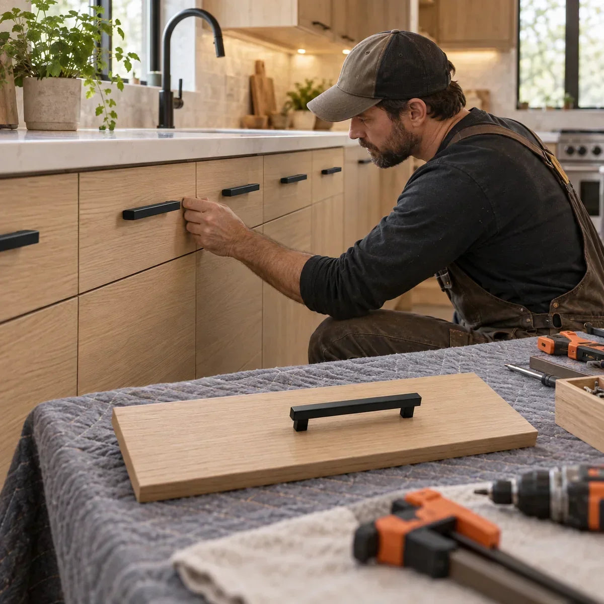
Fivalo workshop technique • Cabinet hardware
One test piece. A more consistent kitchen.
For consistent cabinet hardware placement, choose the position first, measure the actual screw-centre spacing, prove the setup on matching scrap, then repeat from the same reference edges. Clamp a sacrificial backer against the exit face to support the wood as the drill passes through.
A pull can be the right style and still look wrong when its fixing points drift from one front to the next. This guide covers the placement decision and the drilling setup together, so you can check both before making permanent holes. It applies to conventional through-bolted knobs and pulls on solid, plywood or suitably constructed composite fronts. Follow separate instructions for glass, stone, integrated handles and special fixing systems.
Where should cabinet knobs and pulls go?
| Location | Useful starting position | Check before drilling |
|---|---|---|
| Upper cabinet doors | Lower opening corner, opposite the hinges. | Comfortable reach and clearance from adjacent doors. |
| Base cabinet doors | Upper opening corner, opposite the hinges. | Countertop, neighbouring pull and appliance clearance. |
| Shaker doors | Centre across the flat face of the opening-side stile. | Keep the fixing on sound material, clear of the routed profile. |
| Drawer fronts | Centre left-to-right; visually test the vertical position. | Use vertical centring or a consistent top offset deliberately. |
| Deep or wide drawers | Mock up the actual handle before choosing its height or quantity. | Grip comfort and the hardware maker’s fixing recommendations. |
These are starting conventions, not a mandatory distance from every corner. A narrow Shaker stile, an unusually tall door or a deep drawer can need a different arrangement. Use the actual hardware, stand back, and confirm that each handle clears the surrounding surfaces. Measure pull spacing between the fixing centres—not from one end of the bar to the other.
Tools and materials
- The actual knobs or pulls, their fixing instructions, and suitable screws.
- Tape measure or steel rule, combination square, sharp pencil and removable marking tape.
- A compatible cabinet-hardware drilling jig, or a carefully made marking template.
- Drill and a sharp bit of the diameter required by the hardware and guide bushings.
- Matching scrap for the test, a flat sacrificial backer, clamps and padded supports.
- Eye protection and a hand screwdriver for final tightening.
A homemade marking template can transfer locations; it does not automatically guide a drill square. If you use a drilling jig, check its capacity, guide diameter and clamping method against your actual hardware before setup. On a recessed drawer front, support the guide so it cannot rock. Remove the front from the drawer box when that gives safer clamping and a clear drilling path.
Worked example: centre a two-hole pull
Use an 18″ / 457.2 mm wide × 6″ / 152.4 mm high front and a pull with verified fixing centres 4″ / 101.6 mm apart. For a vertically centred pull, both holes sit 3″ / 76.2 mm below the top.
| Reference | Inches | Millimetres |
|---|---|---|
| Front centre from left | 9″ | 228.6 mm |
| Left fixing hole from left | 7″ | 177.8 mm |
| Right fixing hole from left | 11″ | 279.4 mm |
| Both fixing holes from top | 3″ | 76.2 mm |
Formula: left hole = (front width − fixing-centre spacing) ÷ 2. Right hole = left hole + fixing-centre spacing. For a knob, use the selected centre point. Recalculate the centre when drawer widths change; keeping the jig spacing locked does not locate a new centre automatically.
Do not round one hardware size into another. A 5″ pull uses 127 mm fixing centres; a 128 mm pull uses approximately 5.039″ centres. Check the supplied hardware and keep your chosen measurement system consistent.
Step 1 — Mock up the position before making holes

- Confirm the opening side of each door. Mark its top and inside face on removable tape so paired doors cannot be accidentally reversed.
- Temporarily hold the pull or knob at the proposed position with removable putty or a safe mock-up. Check appearance from normal viewing distance and test hand clearance.
- Record the chosen reference edges and offsets. For drawers, mark the individual front’s horizontal centre. Use a square to keep the layout perpendicular.
- Measure the fixing centres on the actual pull and compare them with its instructions. Check that the screws suit the complete material thickness.
Fivalo tip: On a pair of doors, compare a left-hand and a right-hand mock-up together. Mirror the opening-side reference, not an arbitrary workshop “left” edge.
Step 2 — Prove the setup on matching scrap
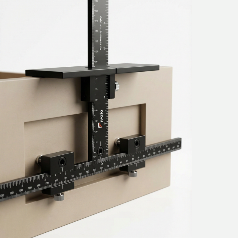
- Set the jig’s fixing centres and edge reference, then tighten its adjustments as instructed. If using a template, establish the corresponding reference marks.
- Clamp matching scrap and a flat backer together. Seat the guide against the intended reference edge without rocking.
- Drill the sample with the correct bit, then trial-fit the real handle. Confirm the screws enter freely and the pull seats without being forced sideways.
- Check the sample position against the mock-up. Only transfer the setup when both fit and appearance are right.
Fivalo tip: A successful sample checks the bit, guide, handle and screws as a system. Keep it beside the bench while you work through the remaining fronts.
For repeated fronts, the Fivalo Cabinet Hardware Jig can help retain a proven spacing and edge reference. Verify that its guide sizes and range suit your hardware. The layout decisions and test piece still come first.
Step 3 — Back the exit face and repeat the setup
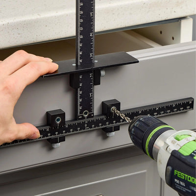
- Protect the finish and clamp the front, guide and sacrificial backer securely. The backer must touch the rear face where the bit exits.
- Check the reference edge and orientation once more. Keep the drill perpendicular and feed steadily through the guide; do not force the bit sideways.
- Ease the feed as you reach the exit. Stop the drill before removing chips or releasing the setup. Inspect the hole before moving on.
- Fit the handle with correctly sized screws. Tighten by hand until secure; stop before crushing the finish, stripping the threads or bottoming out the screw.
Fivalo tip: Inspect the first finished front beside its neighbour before batching the rest. A jig repeats an incorrect setting just as consistently as a correct one.

If the handle does not fit, check the cause
| Symptom | Likely check | Useful correction |
|---|---|---|
| Screws will not enter both threads | Wrong fixing-centre spacing, mixed units or drill drift. | Recheck the actual handle and test piece. Do not force the screws or keep enlarging holes blindly. |
| Pull sits crooked | Different hole heights or an uneven reference edge. | Check each hole against one datum; correct the setup before drilling another front. |
| Back face chips | Unsupported exit, worn bit or heavy exit feed. | Use a sharp bit and a tightly clamped backer, then test matching scrap. |
| Handle stays loose | Screw bottoming out, insufficient engagement or damaged threads. | Match screw length and fixing guidance to the complete front thickness. |
| Paired doors look uneven | Template referenced from different corners. | Compare mirrored opening-side references before drilling. |

Frequently asked questions
Is there one correct distance from the edge?
No. Door style, flat mounting area, reach and surrounding clearance matter. Choose a position, preview it, then repeat it consistently across comparable fronts.
Should I measure the handle’s overall length?
Use the distance between the fixing centres. The bar may extend beyond both mounting posts, so overall length does not locate the holes.
Can I use painter’s tape instead of a backer?
Tape can help mark and protect some finishes, but a firmly clamped backing block physically supports the exit fibres. Test adhesive on an inconspicuous area first.
Can I drill through an attached drawer front and box?
Only if the hardware design calls for that fixing arrangement and you can safely support the exit. Account for the combined thickness, screw engagement and the intended front-adjustment method.
Can one jig setting cover different drawer widths?
It can preserve the pull’s fixing spacing, but each different front width needs the correct centre reference. Recalculate or re-mark the centre rather than indexing every width from the same side offset.

Make the next front match the first
Save the worked example, prove your setup on scrap, and keep that reference beside the job. Explore the Cabinet Hardware Jig when repeated installation calls for a stable drilling guide.
Build your layout skills with our guide to measuring and marking accuracy in woodworking, or explore more Fivalo Timber Tips.
Sources and illustration notes
- KraftMaid: cabinet hardware placement conventions
- Kreg: hardware guide setup and backing-board instructions
The images are AI-generated instructional illustrations of generic workshop setups. They are not photographs of a tested installation or exact Fivalo product models. Use the written measurements and your hardware manufacturer’s instructions; do not measure from a perspective image.
Share:
How to Install Side-Mount Drawer Slides Without Binding